
Free template
Updated
Weld inspection checklist (visual welding inspection)
A weld inspection checklist is the inspector's list of what to check on a welded joint, and visual welding inspection is the first and most used way to check it: looking at the joint with a good light, a weld gauge and a few hand tools, before, during and after welding. Most rejects are made before the arc is struck, by poor fit-up, a dirty joint, the wrong filler or skipped preheat, so this checklist starts there. It has 30 checks in four groups: 10 before welding, 7 during welding, 11 visual checks on the finished weld and 2 for the records. It also has a guide to the discontinuities visual inspection looks for, a weld map report that gives every weld an ID, and a worked example. The accept and reject limits come from your code, never from this sheet. AWS D1.1, the structural steel welding code, sets visual acceptance criteria in a table in its inspection clause (Table 8.1 in recent editions, Table 6.1 in older ones); ASME and other codes set their own. The Excel version keeps the weld map, counts accepts and rejects by welder, and tracks each repair to its re-inspection. It is a checklist for your welders, supervisors and inspectors, not a stand-in for a qualified welding inspector where your code or customer asks for one.
Free to use: print it, copy it and edit it for your team. Enter your name and work email once to download.
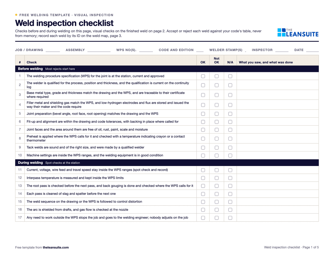 Header fields for the job, drawing, WPS, code and inspector, and the checks before and during welding with OK, Not OK and N/A columns.
When to use it
When to use a weld inspection checklist
- On every code weld: the welder or supervisor runs the before and during checks, and the inspector the checks after welding.
- When a new WPS, welder or fixture starts, on the first assemblies off.
- When weld repairs rise, to see whether the cause sits before, during or after the welding.
- For customer or third-party inspection, as the record of what was checked on each weld.
How to fill it in
- 1
Map the welds
Give every weld on the drawing an ID on a weld map (page 3 of the PDF), with its joint type, size, WPS and the welder who makes it.
- 2
Check before welding
The WPS is at the station, the welder is qualified and current, the material and filler are right, and the joint is prepared, fitted and clean, with preheat where called for.
- 3
Spot check during welding
Settings and interpass temperature against the WPS, the root pass, cleaning between passes and the weld sequence.
- 4
Inspect the finished weld
Once it has cooled as your code requires and is clean: size and length with a weld gauge, profile, cracks, fusion, craters, undercut, porosity, arc strikes and distortion, each judged against your code's table.
- 5
Record accept or reject for each weld
Write the result against the weld ID, and for every reject the discontinuity, where it is and its size.
- 6
Repair and inspect again
Tag the reject, repair it to an approved repair procedure, inspect it again and record both results. Send it for NDT where the drawing or code asks.
What visual inspection looks for
Common weld discontinuities, their causes and where the limits come from
Named the way most codes and inspectors name them. The limits are left out on purpose: they depend on the code, its edition, the loading (static or cyclic) and the joint, so read them from your code's table.
| Discontinuity | What it looks like | Usual causes | Accept or reject |
|---|---|---|---|
| Crack | A line in the weld or the heat-affected zone, along or across the weld | Hydrogen, no preheat on thick or hardenable steel, high restraint, an unfilled crater | AWS D1.1 accepts no crack of any size; check your own code. |
| Incomplete fusion | Weld metal lying on the base metal or the last pass without melting into it | Heat input too low, wrong torch angle, travel too fast, a dirty joint | Check your code; usually rejected where it can be seen. |
| Undercut | A groove melted into the base metal at the toe of the weld | Current or travel speed too high, arc too long, wrong angle | Limited by depth and length in your code's table. |
| Porosity | Round holes in the surface from trapped gas | Oil, rust, paint or moisture; gas flow too low or too high; drafts | Limited by size and count in your code's table. |
| Overlap | Weld metal rolled over the base metal at the toe without fusing | Too much metal, travel too slow, heat too low | Check your code; usually rejected. |
| Underfill or unfilled crater | The weld face or the weld end below the required size | Travel too fast, the arc broken off too quickly at the stop | Check size and crater fill against your code. |
| Excess reinforcement or convexity | The weld face too high or too rounded | Too much filler, travel too slow | Limited in your code's table. |
| Arc strike | A small spot of melted metal outside the weld | Striking the arc on the part, a poor ground connection | Check your code; may need grinding and a further check. |
| Short size or length | Leg or throat smaller than the drawing, or the weld too short | Wrong technique, a missed instruction | Measure with a weld gauge against the drawing and your code's tolerance. |
Crack
- What it looks like
- A line in the weld or the heat-affected zone, along or across the weld
- Usual causes
- Hydrogen, no preheat on thick or hardenable steel, high restraint, an unfilled crater
- Accept or reject
- AWS D1.1 accepts no crack of any size; check your own code.
Incomplete fusion
- What it looks like
- Weld metal lying on the base metal or the last pass without melting into it
- Usual causes
- Heat input too low, wrong torch angle, travel too fast, a dirty joint
- Accept or reject
- Check your code; usually rejected where it can be seen.
Undercut
- What it looks like
- A groove melted into the base metal at the toe of the weld
- Usual causes
- Current or travel speed too high, arc too long, wrong angle
- Accept or reject
- Limited by depth and length in your code's table.
Porosity
- What it looks like
- Round holes in the surface from trapped gas
- Usual causes
- Oil, rust, paint or moisture; gas flow too low or too high; drafts
- Accept or reject
- Limited by size and count in your code's table.
Overlap
- What it looks like
- Weld metal rolled over the base metal at the toe without fusing
- Usual causes
- Too much metal, travel too slow, heat too low
- Accept or reject
- Check your code; usually rejected.
Underfill or unfilled crater
- What it looks like
- The weld face or the weld end below the required size
- Usual causes
- Travel too fast, the arc broken off too quickly at the stop
- Accept or reject
- Check size and crater fill against your code.
Excess reinforcement or convexity
- What it looks like
- The weld face too high or too rounded
- Usual causes
- Too much filler, travel too slow
- Accept or reject
- Limited in your code's table.
Arc strike
- What it looks like
- A small spot of melted metal outside the weld
- Usual causes
- Striking the arc on the part, a poor ground connection
- Accept or reject
- Check your code; may need grinding and a further check.
Short size or length
- What it looks like
- Leg or throat smaller than the drawing, or the weld too short
- Usual causes
- Wrong technique, a missed instruction
- Accept or reject
- Measure with a weld gauge against the drawing and your code's tolerance.
What's on the checklist
The 30 checks before, during and after welding
Ten before the arc is struck, seven while welding and eleven visual checks on the finished weld, plus two for the records. The sheet gives each check OK, Not OK or N/A; the accept or reject limits come from the code your job is built to, never from this sheet.
Before welding
Most rejects start here
- 1The welding procedure specification (WPS) for the joint is at the station, current and approved
- 2The welder is qualified for the process, position and thickness, and the qualification is current on the continuity log
- 3Base metal type, grade and thickness match the drawing and the WPS, and are traceable to their certificate where required
- 4Filler metal and shielding gas match the WPS, and low-hydrogen electrodes and flux are stored and issued the way their maker and the code require
- 5Joint preparation (bevel angle, root face, root opening) matches the drawing and the WPS
- 6Fit-up and alignment are within the drawing and code tolerances, with backing in place where called for
- 7Joint faces and the area around them are free of oil, rust, paint, scale and moisture
- 8Preheat is applied where the WPS calls for it and checked with a temperature indicating crayon or a contact thermometer
- 9Tack welds are sound and of the right size, and were made by a qualified welder
- 10Machine settings are inside the WPS ranges, and the welding equipment is in good condition
During welding
Spot checks at the station
- 11Current, voltage, wire feed and travel speed stay inside the WPS ranges (spot check and record)
- 12Interpass temperature is measured and kept inside the WPS limits
- 13The root pass is checked before the next pass, and back gouging is done and checked where the WPS calls for it
- 14Each pass is cleaned of slag and spatter before the next one
- 15The weld sequence on the drawing or the WPS is followed to control distortion
- 16The arc is shielded from drafts, and gas flow is checked at the nozzle
- 17Any need to work outside the WPS stops the job and goes to the welding engineer; nobody adjusts on the job
After welding: visual inspection
Accept or reject to your code's table
- 18The weld has cooled as your code requires before final inspection, and is clean enough to see the surface
- 19Weld size (leg or throat) and length match the drawing, checked with a weld gauge
- 20Reinforcement, convexity and overlap are within your code's limits
- 21No cracks in the weld or the heat-affected zone
- 22Fusion between the weld and the base metal, and between passes, is complete as far as can be seen
- 23Craters are filled to the full cross-section of the weld
- 24Undercut depth and length are within your code's limits
- 25Surface porosity is within your code's limits
- 26No arc strikes outside the weld, or any found are recorded and dealt with as your code requires
- 27Spatter is removed where the drawing, the coating or the customer asks
- 28Distortion and the assembly's dimensions are checked against the drawing
Records
So every weld can be traced
- 29Each weld has an ID on the weld map, with the welder's stamp or ID recorded against it
- 30A rejected weld is tagged, repaired to an approved repair procedure and inspected again, and any NDT the drawing or code asks for is requested
A filled-in example
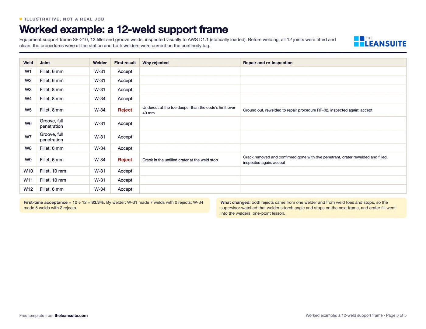
Illustrative, not a benchmarkAn example: visual inspection of an equipment support frame with 12 welds, built to AWS D1.1 for static loading by two welders (illustrative, the same as page 5 of the PDF and the Excel example sheet).
The example frame: 12 welds, 10 accepted first time
- Accepted first time: 10 welds
- Rejected, then repaired: 2 welds
- Welder W-317 of 7 accepted first time
- Welder W-343 of 5 accepted first time
W5 undercut, W9 crater crack
Of 12 welds, 10 were accepted first time and 2 rejected: W5 for undercut and W9 for a crater crack, both by welder W-34. Both passed after repair.
- Before welding: all 12 joints fitted and clean, the procedures at the station, and both welders current on the continuity log.
- W5, an 8 mm fillet by welder W-34: undercut at the toe deeper than the code's limit over 40 mm. Rejected, ground out, rewelded to repair procedure RP-02 and accepted on re-inspection.
- W9, a 6 mm fillet by W-34: a crack in the unfilled crater at the weld stop. Rejected; the crack was removed and confirmed gone with dye penetrant, the crater was rewelded and filled, then accepted.
- The other 10 welds were accepted first time. Welder W-31 made 7 welds with no rejects; W-34 made 5 with 2 rejects.
10 of 12 welds accepted first time, 83.3%. Both rejects came from one welder and from weld toes and stops, so the supervisor watched W-34's torch angle and stops on the next frame, and crater fill went into the welders' one-point lesson.
Common mistakes
Inspecting only the finished weld
By then the cause is buried. Most rejects come from fit-up, cleanliness, filler and preheat, so check them before the arc is struck.
Limits from memory
Undercut and porosity limits differ by code, edition and loading. Keep your code's table at the inspection point.
Inspecting too soon
Some steels can crack hours after welding. Wait as long as your code says before the final visual inspection.
No weld IDs
Without a weld map, a reject cannot be traced to the welder, the joint or the repair.
Repairing without inspecting again
A repair is a new weld. Inspect it again and record both results.
Download the template
Free to use: print it, copy it and edit it for your team. Enter your name and work email once to download.
Run this template in LeanSuite
Audit management in LeanSuite lets you build, schedule and run any shop floor audit or inspection, from layered process audits to gemba walks, and turn every finding into a tracked action.
See it in a 45-minute demoIn the lean glossary
Guides
- Welder continuity log template
- Lean for metal fabrication: welding defects, causes and first checks
- Defect check sheet: tally weld repairs by type
- First article inspection report (AS9102 forms)
- NCR form template
- How to reduce scrap and rework: a worked month
- Manufacturing Defects: Types, Root Causes, and Prevention
FAQ
Weld inspection checklist (visual welding inspection): common questions
Checking a weld by eye, with a good light, a weld gauge and simple tools, against the drawing and the code. It covers the joint before welding, the process during it and the finished weld, and it is the first inspection on almost every weld.
Before welding: the procedure, the welder's qualification, the material, the fit-up, cleanliness and preheat. During welding: settings, interpass temperature and cleaning between passes. After: size, profile and discontinuities such as cracks, incomplete fusion, undercut, porosity and overlap.
They come from the code the job is built to. AWS D1.1 sets them in a table in its inspection clause, split by static and cyclic loading and by tubular connections. ASME and other codes have their own. This checklist leaves the numbers to your code.
When your code, your customer or your contract asks for one. Many shops have welders and supervisors run the before and during checks, and a qualified inspector sign off the final visual inspection.
Not always, because it only finds what shows on the surface. The drawing, the code or the customer may call for NDT on some welds, such as dye penetrant, magnetic particle, ultrasonic or radiographic testing.
More free templates
All templates- 8D report templateD0 to D8 with targets, containment counts, occurrence, escape and systemic causes, verified actions and a worked example.
- Poka-yoke worksheetEach step's errors and what they cost, the device (approach, function, method), payback, and a log that proves each device works.
- Layered process audit (LPA) checklist20 yes, no or N/A checks at the station, a layer and frequency matrix, question banks for four processes and a findings table.
- IATF 16949 internal audit checklist40 audit questions in three parts, one for each internal audit IATF 16949 names (system, manufacturing process, product), each with its clause, the evidence to look for, a core tool tag and a column for the customer's own requirement.
- Process audit checklistAudit one process from inputs to results: 32 questions graded conforms, minor or major, a product check, a score by group and a findings list.
- PFMEA template (process FMEA)Failure modes, effects and causes rated for severity, occurrence and detection, with RPN before and after action.
- Pareto chart templateA tally sheet, the Pareto by count and by cost with the cumulative line and the 80% cut, and a before and after comparison. Excel sorts and draws it.
- Control plan templateWhat is checked at each step, against which limits, how, how often, and what to do when a result is out.
- Corrective action request (CAPA) formOne problem from containment to proof the fix worked, with occurrence and escape causes and a closure check that tells you when it can close.
- ISO 9001 management review kitA 90-minute agenda, data sheet, minutes and action log for the clause 9.3 review, with an Excel planner that flags the next review due.
- Non-conformance report (NCR) formA two-page NCR from the requirement against what was found to disposition and closure, and an Excel NCR log.
- CAPA log templateAn Excel CAPA tracker with status, days open, late flags and counts by source, plus a printable log and monthly review.
- Supplier corrective action request (SCAR) formA SCAR from the problem and containment asked for to the supplier's 8D-style response, verification and closure, with a filled-in example.
- First article inspection report template (AS9102 forms)The three forms in the AS9102 layout (part number, product and characteristic accountability), 22 review checks, the full and partial FAI triggers, and a worked example with one failed characteristic.
- FOD walk checklist (foreign object debris)26 checks for a FOD walk on the production floor in six groups, a FOD found log, an area plan with the route and frequency, and a worked six-week trend of finds per walk.
- Welder continuity log templateA continuity log for welder qualifications with the next lapse date worked out for each process, 20 checks on the records and the log, and a worked example with three welders and one lapse.
- AS9100 internal audit checklist42 audit questions on AS9100D clauses 4 to 10 with the aerospace additions, the evidence to look for and a sample for each area, five grades, a finding and corrective action report, and a worked audit carried through to closure.
- Design FMEA (DFMEA) templateA design FMEA worksheet with S, O, D and RPN before and after action, a class column and a design rating guide.
- PPAP checklistThe 18 PPAP elements with owner, due date and status, the five submission levels and a readiness count.
- Process capability (Cpk) study sheet25 subgroups of readings with Cp, Cpk, Pp and Ppk worked out, control limits to check stability, and a histogram.
- Incoming inspection checklistReceiving inspection checks from paperwork to sample, the sampling plan, the decision, and an Excel log by supplier.
- Supplier audit checklistA supplier process audit of 32 questions scored 0 to 3, with section scores, a rating and the findings.
- Supplier scorecardMonthly PPM, on-time delivery and SCAR measures turned into points, a weighted score and a rating per supplier.
- Pre-shipment inspection checklistThe last check before shipping: part, quantity, labels, packaging, paperwork and photos, then release.
- Defect check sheetTally defects by type and day, with units inspected, defect rates, a location sheet and the week's Pareto.
- QA matrix templateDefect modes against stations in flow order: where each is made and first caught, a weight × occurrence × detection score, an AA to C class and the escapes flagged.
- Is / is not analysis templateWhat, where, when and extent with is, is not, distinctions and changes, then each possible cause tested against every pair and ranked.
- 4M change management sheet (change point)A shift log of every change to Man, Machine, Material, Method or Design, the extra checks after it and when normal checks resume, with a change point board.
- Histogram templateReadings, bins set by the square root rule, a tally and counts, the spec limits drawn and the share out of spec, with the common shapes explained.
- Scatter diagram templateUp to 50 pairs with a group code, r and R², the least squares line, the quadrant count and r for each group.
- Gauge calibration logA gauge register with next due dates and status, a calibration record with as-found and as-left readings, and the steps when a gauge fails.
- Quality alert formA quality alert to post at the line, a sign-off sheet for every shift, and a log of open, expired and closed alerts.
- TQM self-assessment templateThe eight TQM principles in 24 statements you can check on the floor, scored 0 to 4 by several people, with the spread, the top 3 gaps and an action plan.
- Quality circle meeting recordA circle's charter, a one-page record for each meeting and a problem register that follows every problem from selected to closed or escalated.
- Jidoka worksheet (stop at abnormality)For one line or cell, every abnormality that should stop the work: how it is detected, how the work stops, who is called, the immediate fix and the root cause step, plus a log of real stops.
- X-bar and R control chart template25 subgroups with means and ranges, control limits from A2, D3 and D4, signal flags, both charts and a reaction log.
- Gage R&R study sheet10 parts, 2 or 3 appraisers, 2 or 3 trials: EV, AV, GRR, PV, %GRR and ndc by the average and range method.
- Root cause analysis templateOne report from problem statement to proof: containment, evidence, analysis, verified causes, actions and the effectiveness check.
- Quality control pillar 90-day model area planThirteen weeks from the QA matrix to the QM matrix on one model area, a KPI board, the day-90 gate and expansion waves.
- Error-proofing verification log (daily master-sample check)Each poka-yoke device proved every day or week with a known-bad sample, with missed checks counted and the hours and parts at risk worked out when one fails.
- Defect catalogue template with boundary samplesEvery defect with a definition, a class and the reason for it, measured accept and reject limits by zone, boundary samples, a defect log with DPU and Pareto, and an inspector agreement check.
- I-MR chart template (individuals and moving range)Up to 100 single readings with moving ranges, limits from a baseline, five run-rule flags, both charts, a second phase and a reaction log.
- Attribute control chart template (p, np, c and u charts)p, np, c and u charts in one workbook: a chart selector, a sample size check, limits for each subgroup, signal flags and four worked examples.
- HACCP plan template: hazard analysis and CCP worksheetThe Codex 12 steps in one workbook: team and product, process steps checked on site, hazard analysis with the CCP decision tree, the CCP table with completeness checks, an allergen matrix and a verification schedule.
- Mock recall template: traceability exercise worksheetTrace a finished lot back to every input lot and forward to every first customer, reconcile the quantities against a tolerance and time it against your target.
- ISO 9001 internal audit checklist (production area)46 audit questions for the production floor in 11 processes, each with its ISO 9001:2015 clause, what evidence to look for and the sample to take, plus five defined grades, a findings log, a finding report and a summary by clause.
- Food plant GMP inspection checklist (21 CFR 117 subpart B)55 checks in the order of 21 CFR 117 subpart B, each citing its paragraph and saying what to look at, with a grade, finding, owner and due date; results by section and grade, a walk route and a bakery example.
- Master sanitation schedule with pre-op verificationA master list of cleaning tasks by area and equipment with frequency, chemical, lockout, who and next due date, a weekly on-time count, and the pre-operational verification log with a release step.
- Measurement uncertainty budget templateA GUM uncertainty budget: Type A and B rows, divisors by distribution, sensitivity coefficients, uc, νeff, k from the t-table, U, TUR and a guard band check.
- Defect detection matrix templateMap where each defect is created and where it is found, score the gap and move the check closer to the cause.
- APQP checklistThe five APQP phases as a checklist: deliverables, owners, due dates, gate reviews and an issues list.
- Out-of-control action plan (OCAP) templateA reaction plan for a control chart: the steps, what each signal means, who to call and a log of events.
- Quality inspection checklistAn in-process and final inspection record: measured characteristics, visual checks, a decision and first pass yield.
- AQL sampling plan templatePick a sample size, read accept and reject numbers, record the defects and decide on the lot.
- MSA study workbookBias, linearity and stability study sheets for a gauge, with the arithmetic done and a guide to which study when.
- Incoming quality control stage sheetA register that shows how much control each purchased part has and plans the move from your dock to the supplier's process.
- Internal audit schedule templateA year of internal audits planned by risk: the programme, the register, the auditors and the findings.
- Approved supplier list templateThe list of suppliers you may buy from, with the evidence behind each, certificate expiry alerts and re-evaluation dates.
- Pest control inspection checklistA pest control walk-round for a food plant, with a log of traps and stations and action levels for each type of device.
- Cleanroom audit checklist33 cleanroom checks split by how often they run (each shift, weekly, per plan, system), a gowning order to watch against, a differential pressure log and a findings log, with a worked week of readings.
- GMP audit checklist for drug manufacturing42 self-inspection checks ordered by the subparts of 21 CFR 211, each with its section, the matching EU GMP chapter and whether it is seen on the floor or in records, graded critical, major or minor, with a worked audit of a packaging line.
- Line clearance checklist28 line clearance checks in six sections (area, equipment, materials, printed materials, documents, coder and vision settings), cleared by the operator and verified by a second person, with a printed-materials reconciliation and a worked example that does not balance.
- ISO 13485 internal audit checklist38 questions on ISO 13485 clauses 4 to 8, each with the FDA QMSR section that brings it in or adds to it, a production floor tab (records, current instructions, training, nonconforming product, CAPA) and a worked audit of a catheter line.
- ISO 22716 GMP audit checklist for cosmetics25 cosmetic GMP checks following the sections of ISO 22716, split into a floor walk (people, premises, equipment, materials, production) and system checks (lab, out of specification, deviations, complaints, change control, audits, documents), with a worked audit of a filling line.
- SSOP template: sanitation standard operating procedureOne sanitation SOP sheet per area or machine (steps, chemical, contact time, PPE, lockout, owner), a 23-check pre-op inspection and a verification log for visual, ATP and micro checks.
- SQF internal audit checklist for food manufacturing54 questions in the two parts of the SQF manufacturing code (system elements and GMP), each group mapped to BRCGS and FSSC 22000, graded Conforms to Critical, with findings, a score and a yearly plan.
- Injection molding defects chart16 molding defects with causes by machine, material, mold and method, first checks, and an Excel defect log with a Pareto.
- ESD audit checklist29 checks for an ESD protected area, with daily tests split from periodic verification, a measurement log and a worked audit.
- 5S audit checklist template25 checks, five per S, scored 1 to 5, with a score summary and a chart of the five S's.
- 1-1-90 method worksheetOne page: score areas 1 to 5, write the pain point with a before and target number, check days 30, 60 and 90, and plan the next three areas.
- Gemba walk checklistA walk plan and route, 30 prompts in six groups and a findings table with owners and due dates.
- Gemba walk field guideA 20-page pocket guide: the rules, 48 questions by area with good and warning answers, a 30-day route and the follow-through loop, plus an action-log workbook.
- Leader standard work templateA team leader's daily, weekly and monthly routine with a box per day, follow-ups and a weekly review.
- Supervisor leader standard work templateA supervisor's daily, weekly and monthly routine with a box per day, an escalation log and a weekly review.
- Production manager leader standard work templateA production or value stream manager's routine by day, week and month, with an escalation log and a weekly review.
- Plant manager leader standard work templateA plant manager's short routine by day, week and month, with an escalation log and a weekly review.
- Autonomous maintenance (CILR) checklist20 clean, inspect, lubricate and retighten checks with a box per day, an abnormality log and sign-off.
- A3 problem solving templateThe standard seven-box A3 from background to follow-up, with a filled-in worked example. PDF and Excel.
- PDCA templateOne improvement cycle on one page: plan, do, check against the goal, then standardize or adjust. PDF and Excel.
- 5 Whys templateA problem statement, a why chain that can branch, evidence for every answer, root causes and countermeasures that are checked.
- 5W1H templateWho, what, when, where, why and how: a problem statement built from checked facts, and an action plan with nothing left open.
- Skills matrix templatePeople by tasks on a 0 to 4 scale, coverage and gaps per task and shift, and a training plan that closes them.
- Standard work sheet templateTakt time, each element's manual, machine and walk time on a time chart, key points and standard WIP.
- One point lesson (OPL) templateOne topic on one page: wrong way and right way pictures, checkable key points, the standard it belongs to and a sign-off record.
- SMED changeover worksheetChangeover steps with times, internal or external, what can move, ideas and before/after totals.
- Kaizen event charter templateProblem, goal, scope in and out, boundaries, metrics from baseline to target, team and roles, and sign-off before day one.
- RACI matrix template17 kaizen project tasks by 10 roles, with R, A, C, I drop-downs and a check for one accountable per task.
- 5S red tag log and red tagsA log of every red-tagged item with its decision, and six printable red tags to cut out.
- Shift handover templateSafety, production against plan, holds, downtime events, materials and people, and the open actions the next shift takes over.
- Shift schedule packTen shift patterns defined exactly, each with a 28-day calendar, hours worked out from the cycle and a US 40-hour check, plus an Excel roster.
- Kanban card templateSix production and six withdrawal kanban cards to print and cut out, with loop sizing and a card register.
- Idea suggestion formA one-page idea form with the supervisor's answer and points, and an idea log that tracks days to answer.
- Just Do It (JDI) card templateSix Just Do It cards per sheet for quick fixes, with the rules for what counts and a log of every card.
- Quick kaizen templateOne page for a small improvement: before and after, the cause, the countermeasure, the results and whether the standard changed.
- Time study sheetTime each element over 10 cycles and work out the average, lowest repeatable and standard time. Excel does the sums.
- Spaghetti diagram templateSquared paper to trace every trip, a trip log that turns grid squares into feet, meters and walking time, and a before and after comparison.
- OEE tracking sheetOne row per shift for a week. The Excel version works out availability, performance, quality and OEE and charts the week.
- OSHA 300 log workbookA log laid out like OSHA Form 300, a 300A that totals itself, TRIR and DART rates, and an is-it-recordable walk traced to 29 CFR 1904.
- Near miss report formA two-page near miss report from the first report to closure, and an Excel log with status and days open.
- Safety observation card templateFour behavior-based safety cards per sheet, with safe and at-risk checks, the conversation and a tally sheet.
- Job safety analysis (JSA) templateJob steps, hazards, risk scored before and after the controls, the hierarchy of controls, PPE and sign-off.
- Risk assessment matrix template (5×5)A color-coded 5 × 5 severity and likelihood matrix, a scoring guide and a risk register.
- Incident investigation report templateFacts and a sourced timeline, causes at three levels, actions by the hierarchy of controls, a US recordkeeping screen and a closure check.
- Incident report templateThe first report, filled in the same shift: what happened, people, injury or damage, treatment, a US recordkeeping screen, actions and an Excel incident log.
- Toolbox talk templateA record of a short safety talk: topic, key points, questions raised, actions and an attendee sign-in sheet.
- Lockout/tagout (LOTO) procedure templateA machine-specific LOTO procedure: energy sources and isolation points, the steps from shutdown to restart, and the annual review.
- Forklift inspection checklist23 pre-shift checks for a week on one page, a do-not-operate rule, and a defect and repair log.
- Preventive maintenance checklist templateA PM checklist per machine with readings and sign-off, and a PM schedule that works out the next due date.
- Equipment downtime log (MTTR and MTBF)A breakdown and downtime log, with MTTR, MTBF and downtime by machine and cause worked out in Excel.
- Environmental aspects and impacts registerAn ISO 14001-style register of aspects and impacts, with significance scoring, legal requirements, controls and owners.
- Manufacturing process instruction (MPI) templateOperation steps with parameters, tools, quality checks, safety and a photo each, plus revision history and approval.
- Engineering process instruction (EPI) templateScope, parameters and limits, equipment and materials, validation steps, acceptance criteria, change history and approvals.
- Training sign-off sheetAn attendance and sign-off record where each person signs they understood, with a competence check and an Excel log.
- Learning curve and ramp-up workbookBoth learning curve models side by side, a fit from your own observed hours, batch hours, the unit that reaches standard and a weekly ramp plan.
- Operator staffing calculatorTakt, work content, the operators a line needs, a check of your station plan and the roster with absence cover, from your own demand and element times.
- On-the-job training (OJT) checklistThe training record for one trainee on one job: the four TWI steps signed, every try judged, qualified when your rule is met, then tapering follow-up checks.
- New hire onboarding checklist (manufacturing)29 onboarding items from before day 1 to the 90-day review, with owners, dates and review notes.
- Competency assessment formThe one-person assessment behind a skills matrix rating: each task rated 0 to 4 from evidence, checked, with a training plan for every gap.
- Cross-training plan templateWho is learning which task, from and to which level, by when, and how many are qualified on each task.
- Absenteeism tracker templateA monthly attendance grid with codes, absence rate by person and team, and an optional Bradford factor.
- Engineering change request (ECR) formAn ECR form with the change, what it touches, risk and approvals, and an Excel log that tracks each change to done.
- Process flow diagram templateA squared sheet to draw the flow with a symbol key, and a step table that counts operations, moves, checks, waits and storage.
- Office 5S audit checklist25 checks written for offices and shared areas, five per S, scored 1 to 5, with a score summary and actions.
- Floor marking color guideA floor marking color standard with swatches, marks and line widths to fill in, and a floor marking check with a layout sketch.
- Shadow board plannerTool inventory with fetch time, a layout planned from each tool's outline size, a month of daily checks with 5S audit evidence, and a missing tool log.
- Lubrication schedule templateEvery lube point with lubricant, method, amount, frequency and who, with next due dates and a monthly sign-off record.
- TPM tag logEvery abnormality tag with type, who fixes it, priority and dates, with days open and counts by type and week.
- Autonomous maintenance step auditCriteria for each of the seven autonomous maintenance steps, scored 0 to 2, with the step result and the decision to move on.
- Inventory cycle count sheetA blind count sheet with variance and tolerance, an ABC count schedule and record accuracy, worked out in Excel.
- Hour-by-hour production boardHourly plan against actual with running totals and the reason for each miss, plus a shift summary by reason.
- Cost savings trackerA savings log with hard and soft savings, payback and Finance's sign-off, plus a glide path against the year's target.
- CapEx request formA capital request with options, costs, benefits, payback and NPV, and the approval levels the amount needs.
- Standard cost variance workbookEight standard cost variances from your standards and actuals, favorable or unfavorable, proved against actual cost, with the questions to ask on the floor.
- Cost-benefit analysis templateUp to three options side by side with costs, hard and soft benefits, payback, NPV and the benefit-cost ratio.
- Cost of poor quality (COPQ) worksheetCost of quality by prevention, appraisal, internal and external failure, with COPQ as a share of sales.
- Receiving logA dock receiving log with quantities, damage, QC holds and putaway, plus a discrepancy report and dock-to-stock time.
- Warehouse safety inspection checklistThirty warehouse safety checks from aisles to fire exits, marked OK or Not OK, with an action for every finding.
- Pallet racking inspection checklistRack checks per aisle with a green, amber and red damage rating, and a damage log with repair dates.
- Material shortage logEvery part short with its need date, line impact, ETA and escalation, and counts by reason and supplier.
- Safety audit checklistThirty-four plant-wide safety checks answered Yes, No or N/A, scored by area, with a risk rating and an action for every No.
- Ergonomic risk assessment checklistScreen a task for 21 ergonomic risk factors, score how long each lasts, and rank tasks so the worst get controls first.
- Work order template for maintenanceA work order template for maintenance: one form per job from request to handback, and a log of response, completion and backlog by priority.
- Six big losses worksheetWhere a machine's planned time goes: the six big losses in minutes, ranked, with A, P, Q and OEE worked out.
- Andon response logEvery andon call with response and fix times, flags against your targets, and counts by type and station.
- Changeover checklist25 checks for every changeover, a record of planned and actual times, and a log of changeover time against target.
- Kanban sizing calculatorHow many kanban cards each loop needs, per part, with the change from today's cards and what the loop holds in days.
- Kaizen event trackerEvery kaizen event on one sheet: status, roles, the metric against target, open actions and the 30, 60 and 90 day checks.
- Standard work audit checklist24 checks of a job against its written standard, ten timed cycles, and each gap sorted by cause before anyone acts.
- TWI job breakdown sheetThe TWI Job Instruction breakdown of a job into important steps, key points and reasons, with a worked example and the four steps.
- Standard work combination tableOne operator's manual, machine, walk and wait time on a time chart against takt, with machine cycles and a process capacity sheet.
- Lead time worksheetProduction lead time from the inventory waiting at each step, value-added time and process cycle efficiency, plus an order traced from order to delivery.
- Waste walk checklist (TIMWOODS)32 things to look for across the eight wastes, with where and how much, and a findings log with dot votes, owners and dates.
- Maintenance KPI trackerMTBF, MTTR, availability and PM compliance per asset and month, plant figures from the totals, planned maintenance % and backlog in weeks.
- Daily huddle agendaA 15-minute start-of-shift stand-up in six timed blocks, with yesterday's SQCDP results, today's plan, actions and escalations.
- DMAIC project charter templateThe Define-phase charter on one page: problem and goal, metrics, scope, team and phase dates, with savings and a tollgate checklist.
- Water spider route plan (mizusumashi)A water spider's fixed route: stops with arrival times, what is delivered and collected, route time against the cycle, cart load and a trip log.
- Cost deployment matrixWCM cost deployment on paper and in Excel: loss quantities by process, causal and resultant losses, the cost of each loss, a Pareto and the projects that recover them.
- Equipment criticality analysisAssets scored 1 to 5 on six criteria with your own weights, ranked and sorted into classes A, B and C with a safety override and a suggested maintenance strategy.
- Bottleneck analysis worksheetEffective capacity per station from cycle time, parallel units, availability and yield, the bottleneck, takt and utilization, a queue cross-check and the five focusing steps.
- Fault tree analysis templateA drawing area with the FTA symbols, an event table with probabilities and minimal cut sets, and the gates worked out bottom-up in Excel.
- 5G investigation sheetConfirm the facts before naming a cause: 5W1H, the five G's with 20 prompts, the gap against the principle and the standard, and the countermeasures.
- Yokoten tracker (horizontal deployment)Copy a proven improvement line by line: the source result, each candidate's own before and after, its share of the source's improvement and the standard updated.
- Coaching kata template (improvement kata storyboard)The learner's storyboard (target condition, current condition, obstacles, PDCA cycles) and a fold-over card with the coach's five questions.
- SMART goals templateWrite a goal, test it against the five SMART letters, then track progress toward the target against the time used.
- Lean readiness assessment templateTwenty statements in four factors, scored 1 to 5 by several people on their own, with averages, the spread between them and the actions.
- Nemawashi template (stakeholder plan)Plan the one-to-one conversations before a decision: who to talk to in what order, their concerns, what changed and where they stand.
- Breakdown analysis reportOne equipment breakdown from the stop to the 90-day check, plus a breakdown log with repeat flags, MTBF and MTTR by asset and a Pareto of causes.
- Heijunka box planner (production leveling)Weekly demand turned into containers a day, takt, pitch and slots, a leveled sequence of products and the heijunka box, with a check that the changeovers fit.
- Future state value stream map worksheetThe eight future-state questions worked through in order: takt, pitch, flow, supermarkets, the pacemaker and the mix, with an EPEI check and current against future lead time.
- Value stream plan (VSM action plan)The future-state map cut into loops, each with an objective and a measurable goal, and its kaizen bursts turned into owned, dated projects on a 12-month timeline.
- Kaizen project plan (Gantt chart)One improvement project as a Gantt chart: tasks by phase with owners, predecessors and working days, a 16-week grid, milestones and a status from planned against actual % done.
- Escalation matrix templateWho is called for each type of issue and after how long, with severity rules, contacts and an escalation log.
- Visual management audit checklist29 checks of whether anyone can tell normal from abnormal at a glance, scored by group, with a trend and actions.
- Employee recognition program templateDesign a recognition program on one page, then run it: points per action, prizes, budget, a points ledger, a monthly leaderboard and a fairness check by team and shift.
- Lean transformation roadmapA plant-wide lean program on one sheet: six phases with exit criteria, six workstreams by quarter over 24 months, the model line, metrics with baseline and target, cadence and risks.
- Obeya room plannerPlan the walls, owners, cadence, agenda and rules of an obeya, then run the weekly review of KPIs, problems, actions and milestones.
- Paper forms inventory (paperless manufacturing worksheet)Every paper form, checklist and log in one list: hours a month, who acts on it, how long the paper waits, and which forms to move first.
- Continuous improvement software evaluation scorecardCompare CI software vendors: a must-have gate, eight weighted criteria scored 1 to 5, points out of 100 and a rank, with a demo script and reference questions.
- Lean principles assessment templateThe five lean principles as 25 things you can see on one value stream, answered yes, partly or no on a walk, with a score per principle, the next step and a trend over walks.
- Employee engagement survey templateA short anonymous pulse survey for shop floor staff: 14 statements in six drivers, two open questions, results by driver and team, and the actions.
- Hansei reflection sheet (lessons learned)A written look back at one finished project, event or launch: goals against results in numbers, causes rather than blame, lessons to keep or change, and where else they apply.
- Safety cross calendarA month drawn as the green cross, colored each day by the most serious safety event, with totals and days since the last injury.
- Daily kaizen routine boardA team's 10 to 15 minute daily routine at the board: one problem from each person, small fixes with one owner, counted every week.
- Weekly maintenance schedule templateNext week's maintenance jobs, scheduled only when ready, loaded against each craft's hours by day, with schedule compliance and break-ins at week end.
- Operational excellence assessment templateThe ten principles of operational excellence as 30 behaviors and practices you can see, scored 1 to 5 by several people, with the spread, the three lowest principles and an action plan.
- Scrum meeting agenda templateTimed agendas for the five scrum meetings, a sprint planning sheet, a retrospective sheet, and an Excel sprint backlog with a burndown.
- Toyota Production System (TPS) house templateThe TPS house for one plant or value stream: roof, two pillars and foundation, with what you do today, the evidence, a status and the next step for each element.
- EPEI and batch size calculatorHow often each part can come round on a shared machine (EPEI) and how big each batch must be, from demand, cycle times and changeovers, now and after SMED.
- People, process, technology (PPT) assessmentCheck one change before go-live: 18 people, process and technology statements scored 1 to 4 by the people who will use it, the lowest element and the actions.
- Process capacity sheet templateEach machine in a part's routing with manual, auto and tool change time, its capacity per shift, and the step that limits the cell against demand.
- Team charter templateA one-page charter for a standing team: purpose, scope, roles, the KPIs it owns, which decisions it makes itself, norms and cadence.
- Chaku-chaku line plannerPlan a load-load cell: time each machine, load and walk, check that every machine is ready when the operator comes back, compare the cell cycle with takt and size the crew.
- Standard operating procedure (SOP) templateA full SOP in the hierarchical step format, from purpose and scope to the steps, records, revision history and approvals, with review checks and an SOP register.
- Process improvement method selectorEight questions about one problem, an example rule that suggests a method and a matrix of nine methods: when each fits, the usual team and time, and the template to start with.
- Safety pillar 90-day model area planThirteen weeks from the incident pyramid to safety standards on one model area, a KPI board, the day-90 gate and expansion waves.
- Autonomous maintenance 90-day model area planAM steps 0 to 3 on one model machine in 13 weeks, a KPI board, the day-90 gate and expansion waves for months 4 to 12.
- Professional maintenance (PM) 90-day model area planThirteen weeks from breakdown analysis to a running PM calendar on one model machine, a KPI board, the day-90 gate and expansion waves.
- Environment and energy pillar 90-day model area planThirteen weeks from waste and energy maps to area standards on one model area, a KPI board, the day-90 gate and expansion waves.
- Focused improvement 90-day model area planThirteen weeks from the loss Pareto to standardized fixes on one model line, a KPI board, the day-90 gate and expansion waves.
- Logistics and customer service pillar 90-day model area planThirteen weeks from the current-state map to pull on one model value stream, a KPI board, the day-90 gate and expansion waves.
- People development pillar 90-day model area planThirteen weeks from the skills matrix to trained cover on critical tasks in one model area, a KPI board, the day-90 gate and expansion waves.
- Early equipment management 90-day model area planThirteen weeks from lessons on current machines to a tracked start-up on one model equipment project, a KPI board, the day-90 gate and expansion waves.
- Cost deployment pillar 90-day model area planThirteen weeks from the loss map to costed, ranked projects in one model area, a KPI board, the day-90 gate and expansion waves.
- Moving from Excel to one system checklistA 34-point checklist and a file inventory for moving trackers from spreadsheets to one system: keep, move, connect or retire, clean, pilot, run both, retire.
- Prioritization matrix templateScore up to 20 improvement ideas on weighted criteria, rank them, test the ranking with equal weights and place each one on an effort and benefit grid.
- Cost per unit worksheet (manufacturing cost per good unit)One product's cost per good unit by materials, labor, machine and overhead, the gap to target, and which cost lever is worth most a year.
- Digital manufacturing readiness assessmentScore 24 statements on process, technology and people from 0 to 4, check the balance between them and rank the gaps by what matters in your plant.
- Manufacturing KPI dashboard templateWeekly plant numbers in, 14 KPIs out: OEE and its parts, first pass yield, scrap, on-time delivery, recordable rate, cost and absence, each against a target.
- RCM worksheet (failure mode and task selection)Failure modes classed as hidden, safety, operational or non-operational, then a task chosen for each: condition-based, discard, failure-finding, redesign or run to failure.
- Training matrix template with expiry datesPeople by required trainings with expiry dates, OK, due, expired and missing flags, compliance by person and area, cover per training and a renewal list.
- Downtime reason codes template26 starter codes mapped to the six big losses, a log with drop-downs, a Pareto by code and by loss, and a code card for the line.
- Kaizen event preparation checklistEverything that has to be ready before a kaizen event and done after it: 44 items with owners and due dates from 6 weeks before day 1 to 30 days after, five go or no-go gates and a day-by-day agenda.
- Critical spare parts list and stocking levelsAssets ranked by consequence, each part classed and given a stocking policy, and min and max worked out from usage and lead time, with the downtime each stock-out would cost.
- Tier 2 meeting agenda and escalation sheetA 15-minute tier 2 agenda in ten timed blocks, fixed roles and rules, escalation triggers with time limits, and a log that ages every escalation and sends the answer back down.
- Forklift operator training and evaluation recordPer-operator training and evaluation record, a register with three-year due dates and refresher triggers, and a weighted practical evaluation scoresheet.
- REBA worksheet (Rapid Entire Body Assessment)Score up to six postures with REBA: body-part drop-downs, Tables A, B and C as lookups, final score and action level, and a before and after comparison.
- ISO 45001 internal audit checklist44 audit questions for the plant floor in 16 safety topics, each with its ISO 45001:2018 clause, the evidence to look for and the sample to take, plus 12 worker interview prompts, a findings log and a summary by clause.
- Plan for every part (PFEP) templateOne row per part: supplier, pack, container, usage, lead time and locations, with ABC classes, market and line kanban counts and a lineside space check.
- Changeover matrix templateA from-to matrix of changeover minutes with the clean each transition needs (allergen, colour, format), and a weekly planner that totals the order and suggests a shorter one.
- Overhead crane inspection checklist: frequent and periodic34 crane checks tied to OSHA 1910.179: an operator's pre-shift card, frequent and periodic inspections with signed records, a deficiency and tag-out log, and a register of next due dates.
- Maintenance job plan templateOne job planned on one sheet: steps and craft hours, parts checked against stock, tools, lockout and permits, documents, a ready check for the schedule, and technician feedback.
- Video time study filming checklistA pre-shoot checklist and shot log for filming a time study on video: camera, light, people, settings, power and review.
- Reorder point and safety stock sheet (many parts)Safety stock, reorder point, order quantity and an order list for up to 500 parts, worked out from each part's own demand and lead time history.
- OSHA compliance calendar (general industry)37 recurring federal OSHA duties with the paragraph, interval, owner, next due date and an overdue flag, plus a 12-month view and counts by owner.
- TRIR and DART rate trackerMonthly hours, OSHA 300 case counts and near misses in; rolling 12-month TRIR and DART rate, a case budget against your target and a trend chart out.
- Energy use and EnPI trackerMonthly electricity, gas and fuel in one unit, a 12-month regression baseline, expected against actual energy for each month, an EnPI ratio, the running saving and the tests that say whether the model can be trusted.
- FIFO lane sizing sheetThe maximum for a FIFO lane from the stop it must cover, in whole containers, with length, refill and wait checks for up to eight lanes.
- Pugh matrix templateCompare up to 8 concepts with a datum as better, same or worse on up to 12 criteria, flag must-haves, and carry the strongest into a second round.
- Machine guarding inspection sheetA machine register with due dates and a status per machine, 21 checks tied to OSHA 1910.212, .219 and .147, a guard opening check against Table O-10, and an action log.
- Condition monitoring route sheetA route of measuring points with baselines, alert and alarm limits, a check interval from the P-F interval, readings with rising and overdue flags, and an exceptions list worst first.
- Fire extinguisher inspection checklist and logThe 8 monthly checks for each portable extinguisher, plus a log with the hydro test interval from OSHA Table L-1, annual and 6-year due dates and open issues.
- Quad chart templateA project on one page in four boxes: idea and owner, problem, approach, and cost, schedule and result.
- Toolbox talk topics (52 weekly topics)52 weekly toolbox talk topics, each with a one-line key message and a discussion question, and a tracker for the year.
- Loss tree worksheetBreak one big loss number into area, line, machine, loss type and cause, and stop at the cause a team can fix.
- Equipment register templateOne row per asset, with hierarchy, criticality, PM strategy and owner, and a check that flags what is missing.
- Machine history record templateOne record per machine: components and their life, every breakdown and repair with cost, MTBF and MTTR, and a repair-or-extend check.
- Compressed air leak survey logWalk sheet, printable leak tags and a tracker that puts an annual cost on every leak and follows it to a verified fix.
- Project savings validation checklistThe gate between a project's claim and a reported saving: 20 checks, a claims register and a six-month sustainment check.
- Life cycle cost analysis templateCompare up to three machines over ten years: price, energy, upkeep, failures and down time, discounted to present value.
- Equipment design review checklistGate reviews for a new machine before order, before build and before start-up, with a safety buy-off and a problems journal.
- Emergency action plan templateA written emergency plan for a plant: site facts, roles and backups, warden coverage, scenario steps and a drill record.
- Preliminary hazard analysis (PHA) worksheetFind and score the hazards of a new line, machine or process before design is fixed, then choose controls and re-score.
- Risk register templateOne scored list of operational risks with owners, actions and dates, a heat map and a review log.
- Hot work permit templateA hot work permit with a precautions checklist, fire watch record and close-out, plus an Excel permit log.
- Confined space entry permit templateA confined space entry permit with checks, an air test log, an entry log and cancellation, plus an Excel register.
- Energy loss matrix templateSeven types of energy loss by six energy sources with a cost in each cell, an action plan and an idle-period shutdown checklist.
- Management safety tour formA leader's scheduled safety walk: observation form, operator interview, tally, actions, rota and a tour log with a dashboard.
- Hazard prediction worksheetA pre-task worksheet: score what could go wrong at each step of a job, add a countermeasure and score again.
- Chemical inventory and SDS register templateA register of every chemical on site with its hazard class, safety data sheet and label, and a check that incompatible products are kept apart.
- Safety committee meeting minutes templateMinutes for a safety committee: attendance, nine agenda items, an action log that carries open actions forward, and monthly numbers.
- Environmental compliance audit checklistAn internal environmental audit: 37 questions with what to look for, a findings log with classes and a score by section.
- Management of change formA change request and review form for a plant: what changes, the hazard review, approvals, pre-startup review, training and close-out.
- Silica exposure control plan templateA written silica plan for general industry: tasks, controls and housekeeping, plus monitoring, medical surveillance, training and a 31-check plan audit.
Can't find the template you need?
Tell us what you're looking for. We'll make it and send it to your inbox, free.
A shift handover sheet, a red tag log, a changeover checklist for one machine: if your team uses it on the floor, ask.